SAFE interface for Kidde CO/Smoke alarms
How I set up my home's smoke detectors to buzz my phone, with a battery backup
The Boards
The goal is to have my phone buzz/get an email when the smoke alarms in the house go off. The alarms I have are Kidde brand, dual smoke and CO detectors. All are wired on the same circuit with A/C power, and have a signal wire tying them together as well. I bought the Kidde interface boards, which tie into the 3 wire interface on the alarms, and toggle a relay when any of the detectors alarm. The Smoke alarm is P/N SM120X and the CO alarm is P/N CO120X.
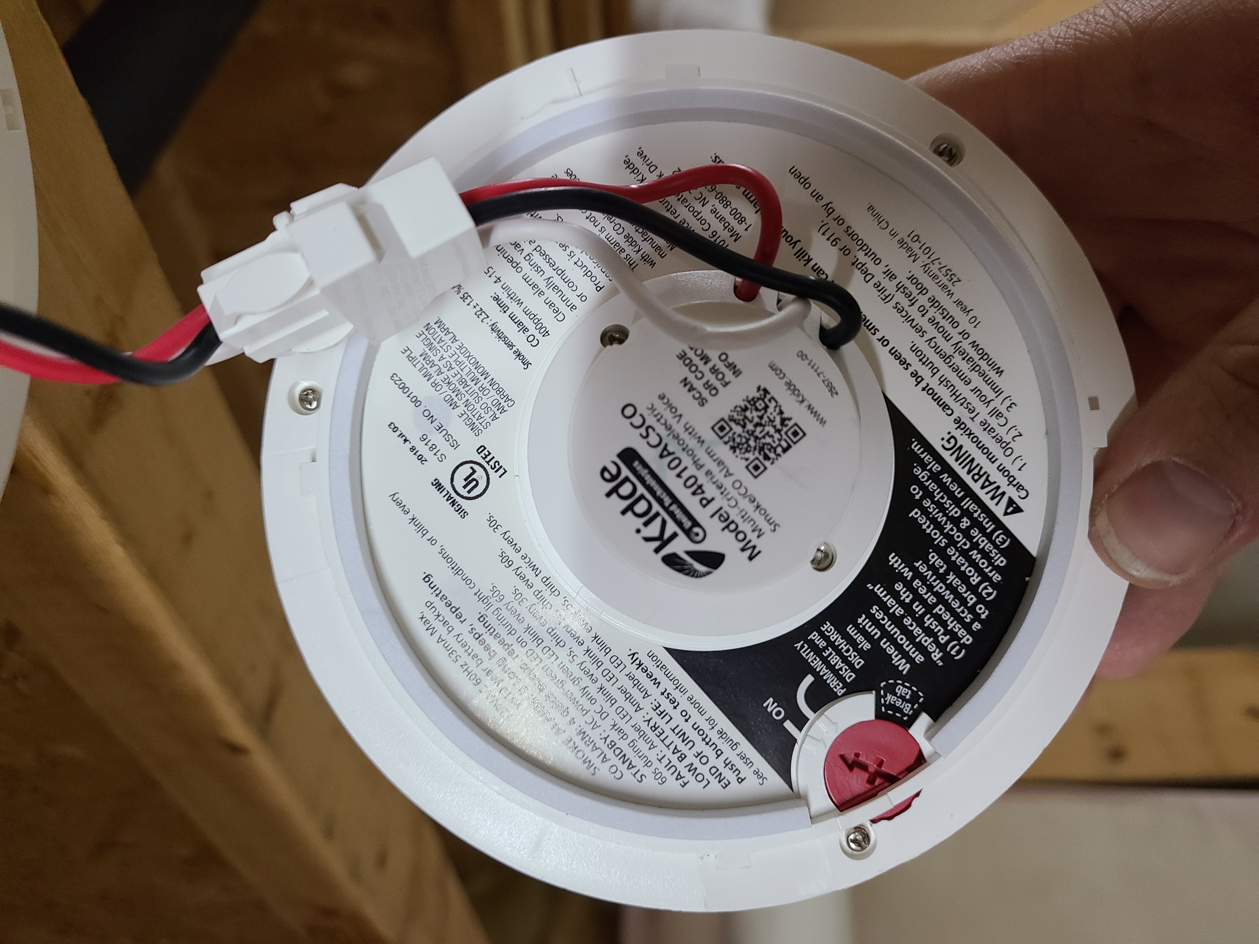
The problem I need to solve is: these boards are AC power ONLY, there is no way to interface backup power to these alarm boards. The smoke alarms have batteries, and my HomeAssistant system (which is what I will be using to alert my phone) is on a conventional computer UPS, so if the power were to go out, the only link between the alarms and my system would die. I need to find a way to add some amount of energy storage to keep the interface going for at least an hour or so.
I took apart the relay boards (meaning I cut the shrink wrap off,) and this is what I found:
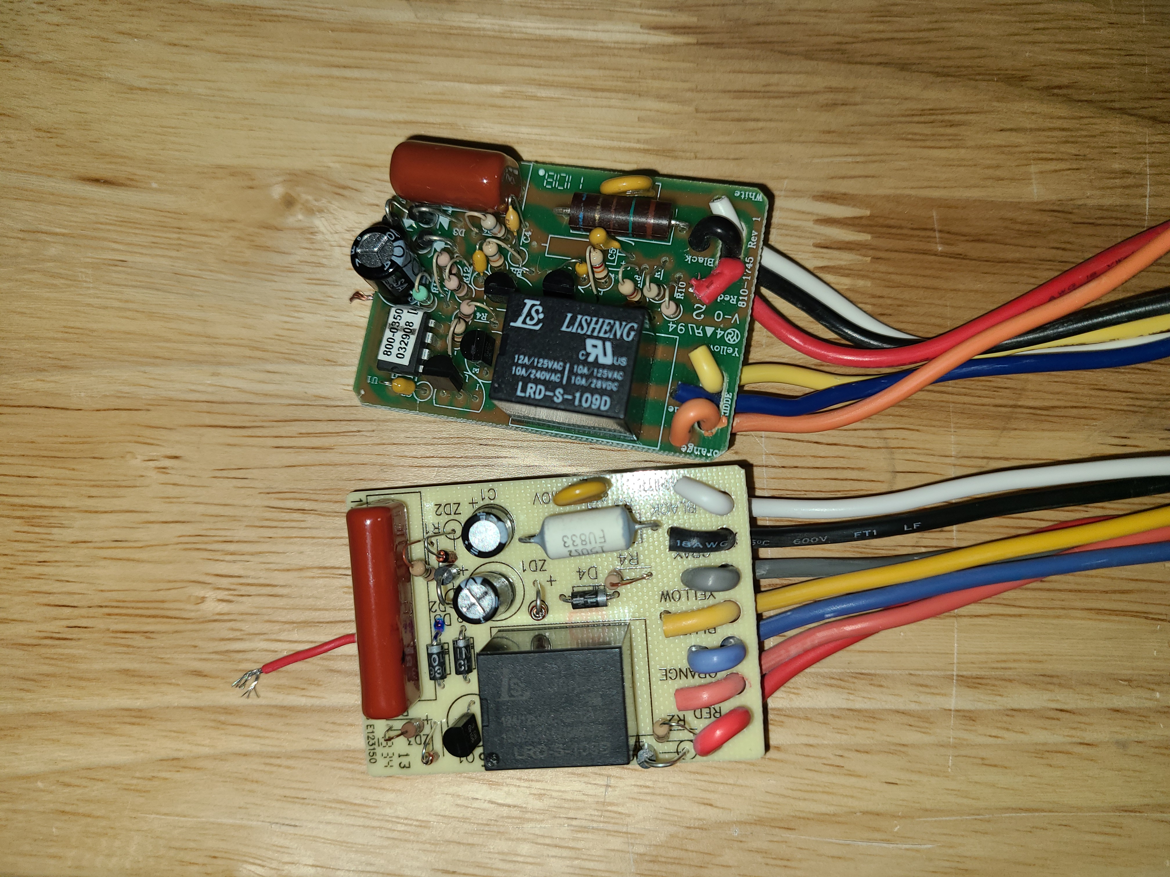

Top baord is the CO alarm, bottom board is smoke alarm. The CO alarm looks a bit more complicated, because it is. The smoke alarm signal is a simple high/low signal on the RED wire, with some filtering to keep the CO signal from triggering it, so it is pretty straightforward. But the CO alarm has to run it's signal on the same wire, so to differentiate between CO and smoke, the CO alarm is actually sending serial data, which requires a chip to decode.
The boards are both powered via capacitive dropper circuits. A short and sweet explanation of a dropper circuit, is that capacitor is placed in series with the rectifying diode, and it essentially acts as a resistor to drop the voltage at the diode, but instead of burning the energy as heat, it is stored in the capacitor, and dumped back into the grid on the negative half of the AC wave. This also means that "ground" or 0V is the white AC neutral wire, the boards are in no way isolated from the mains voltage.
But what all that also means is that there is a DC power rail somewhere on these boards, and in the pictures above, there are test wires soldered to them. On a meter, the power consumtion was 26mA/31mA for the two boards (smoke/Co respectively) with relays active, and less than 5mA each when idle.
The DC rail voltage at the tap points varies wildy. At idle, the voltage is about 12.2V, but when the relays activate, that drops to 9.0-9.5V (Capacitive droppers are Very Stable, just the best...)
I decided that the best idea is to power the boards directly from an external 12VDC source, bypassing the dropper circuit and keeping line voltage out of the box entirely, for safety reasons.
With this setup, the only wires running to the detectors are the neutral wire, and low voltage signal wire. The live 120V is never brought close to the circuit.
The 3 relay contact wires ARE SAFE to handle with power applied, as these are run DIRECTLY to the NO/NC/COM contacts on the relay, and are isolated from the rest of the circuit. There is no voltage on the wires (they are "dry contact" leads).
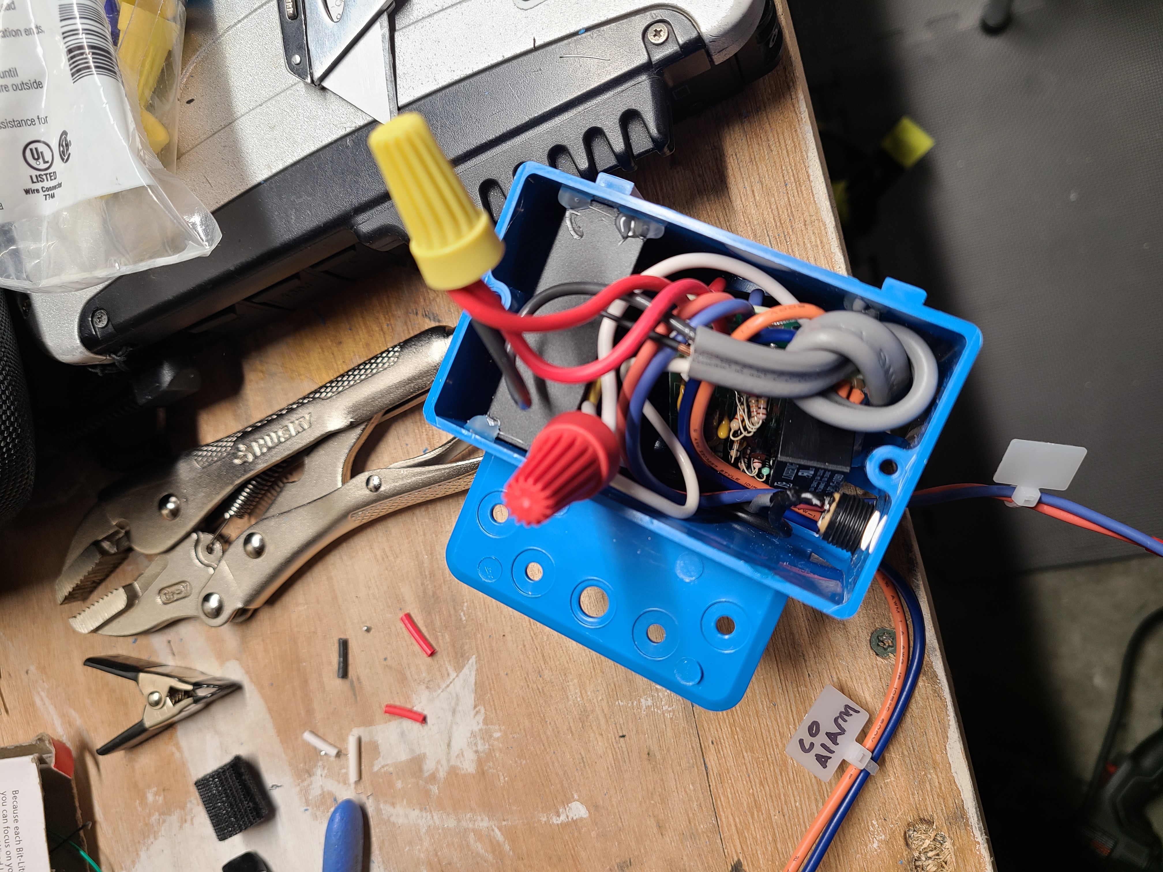
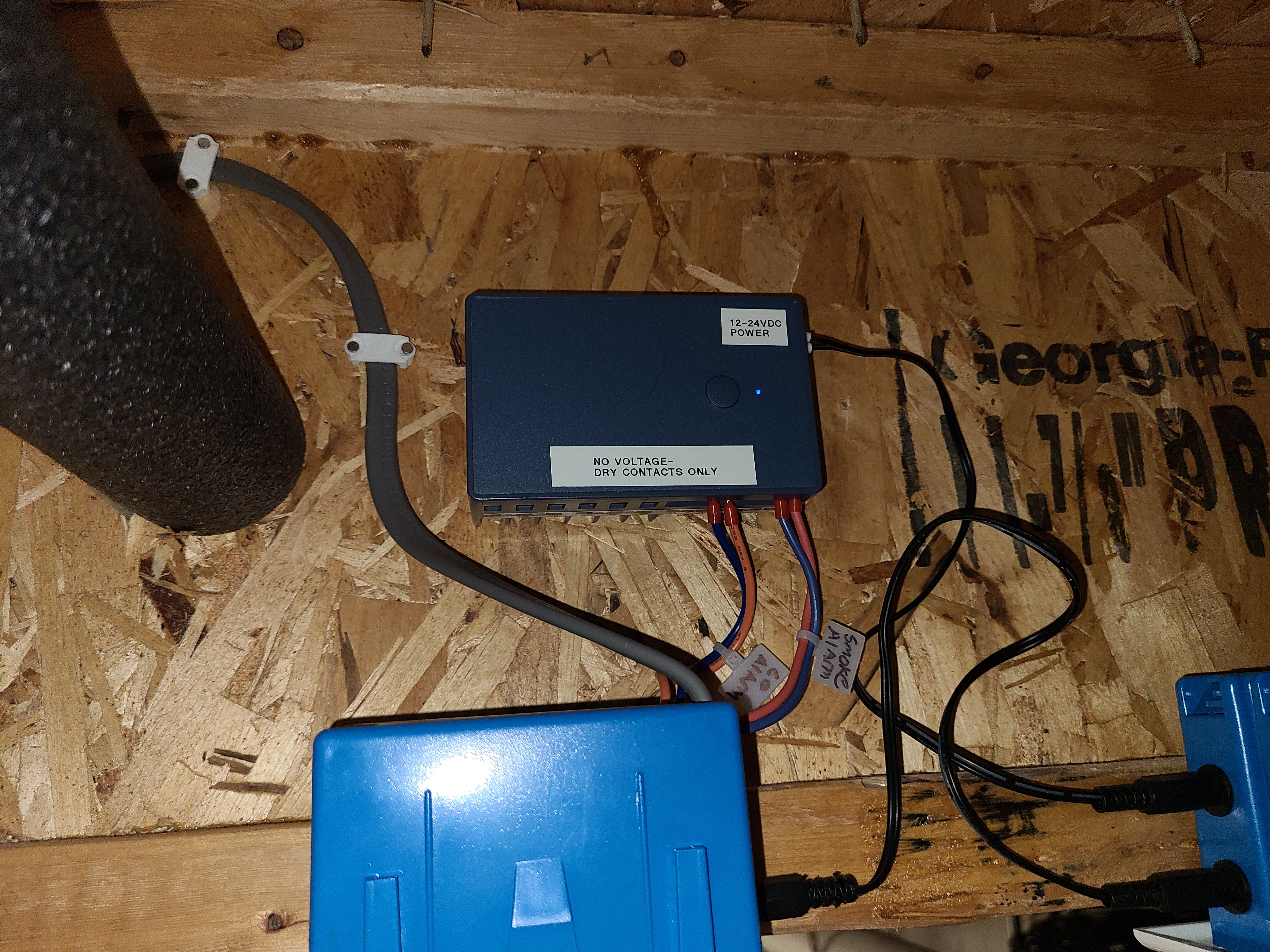
I shoved both relay baords into an electrical box, with the 12V power supply, and of course a plastic shim between the boards to prevent accidental contact.
The DC source I installed with the alarm baords is the PYB10-Q24-S12-U DC-DC converter. It has wide source input range (9-36V) and has a sufficient current output (833mA) at 12V to supply both boards. Most importantly, it has 1.5kV isolation between input and output, which I wanted to isolate the boards as completely as possible from the UPS and PC interface (since the boards are still techinically tied to the mains via the neutral wire, there is a chance for electric shock, however slim, unless isolated.)
With a properly isolated power supply, there is a sort of imaginary line drawn that keeps the UPS and interface box isolated from mains power, meaning they are safe to handle without cutting off the whole circuit at the breaker for UPS battery maintenance or rebooting the interface.
The UPS
I figure that, since the alarms have batteries, and my whole home automation system that I made these alarms report to is also on a conventional computer UPS, I decided this system also needs a battery backup. I chose a no-name generic 18650 Lithium cell UPS:
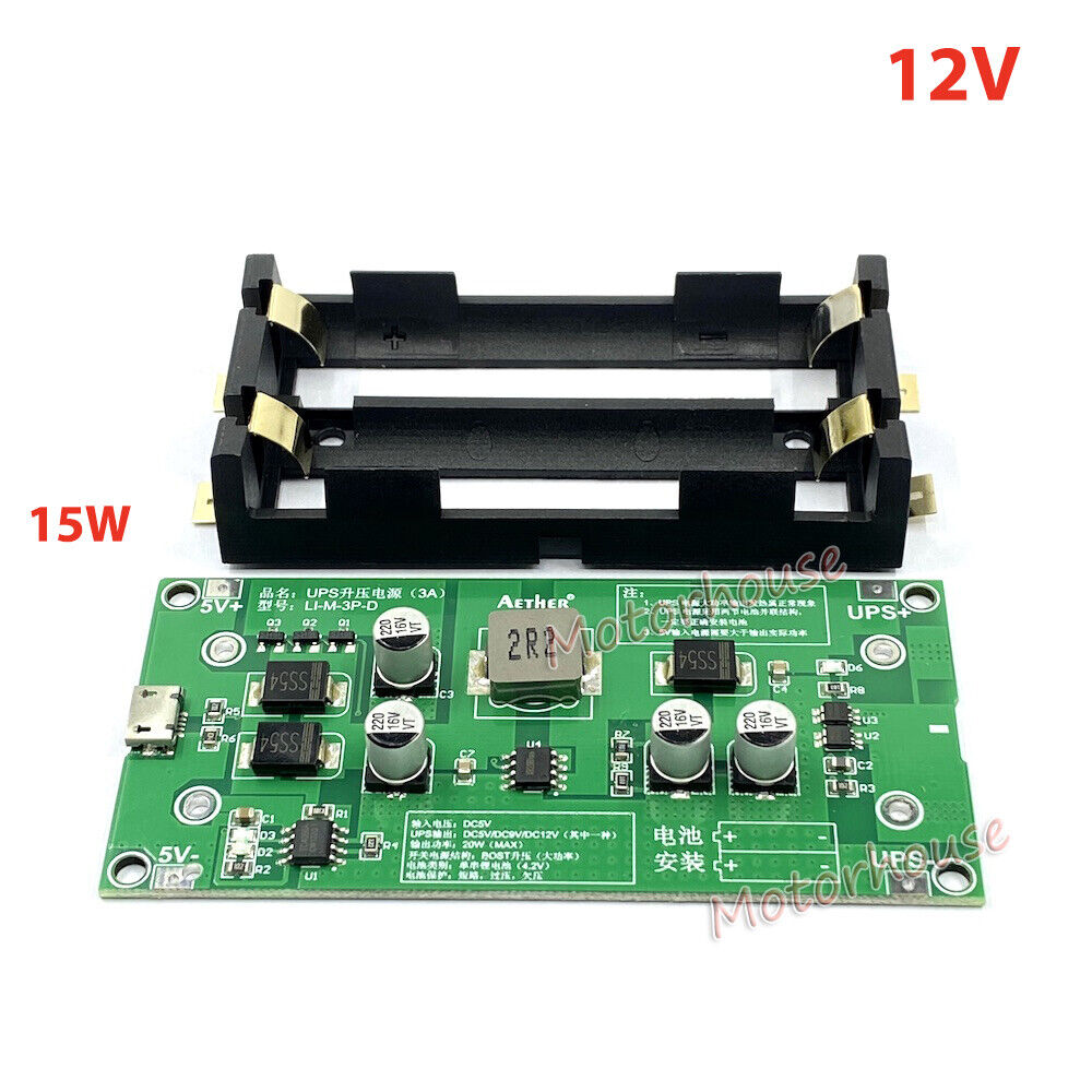
You can find them all over eBay and the like: It can be charged from a 5V/2A USB power supply, which I have far too many of already, and outputs a steady 12V at 1.2A (max). Simply install your preferred brand and capacity of 18650 cell and off it goes. I installed this UPS into an AC outlet box with a blank cover plate, and added a panel mounted USB port for charging, and two DC barrel jacks in parallel for 12V output power. All this barely fit in by putting the UPS board in at an angle. Note also that I had to solder the battery holder onto the board, the UPS came in 2 halves like in the picture above.
I also desoldered the 3 indicator LED's on the board (red on/off, red charging, green fully charged), and added flying-lead LED's, which I then glued to the blank plate where I had drilled 3 holes for the lights to shine through.
With this setup, I am able to mount the UPS anywhere in my unfinished basement, in this case next to the basement alarm, and run the whole setup from an easily replaceable USB power brick.
The PC interface
The device that interfaces these alarm boards with my server, and my phone, is the Zooz Zen17 Universal Relay.
I chose this product specifically to interface with my Z-wave network, a low power short range 900MHz wireless network for home automation. This device is also very cheap (considering the amount of I/O and the general cost of Z-Wave devices) and can run on 12-24V DC as well as USB power.
The Zen17 has two each inputs and outputs: two line-voltage rated relays, and two sets of "dry contact" inputs (two sets of "common 0V" and "sense" pins, and when they are shorted together, the input is detected as "on".)
A useful feature of this device is that the two S1/S2 inputs can be specifically designated as generic smoke and CO alarm senors. This is set in the Z-wave configuration for the device, which I won't go into here.
By default the inputs and outputs are tied together: input 1 is triggered, and relay 1 is activated. The state of the inputs is monitored on the Z-wave network, and relays can also be triggered manually via the network (and in my case, HomeAssistant). I also changed the configuration to separate inputs and outputs, since I am not currently using the relays to do anything, having them activate with the alarms just adds uneeded wear and tear.
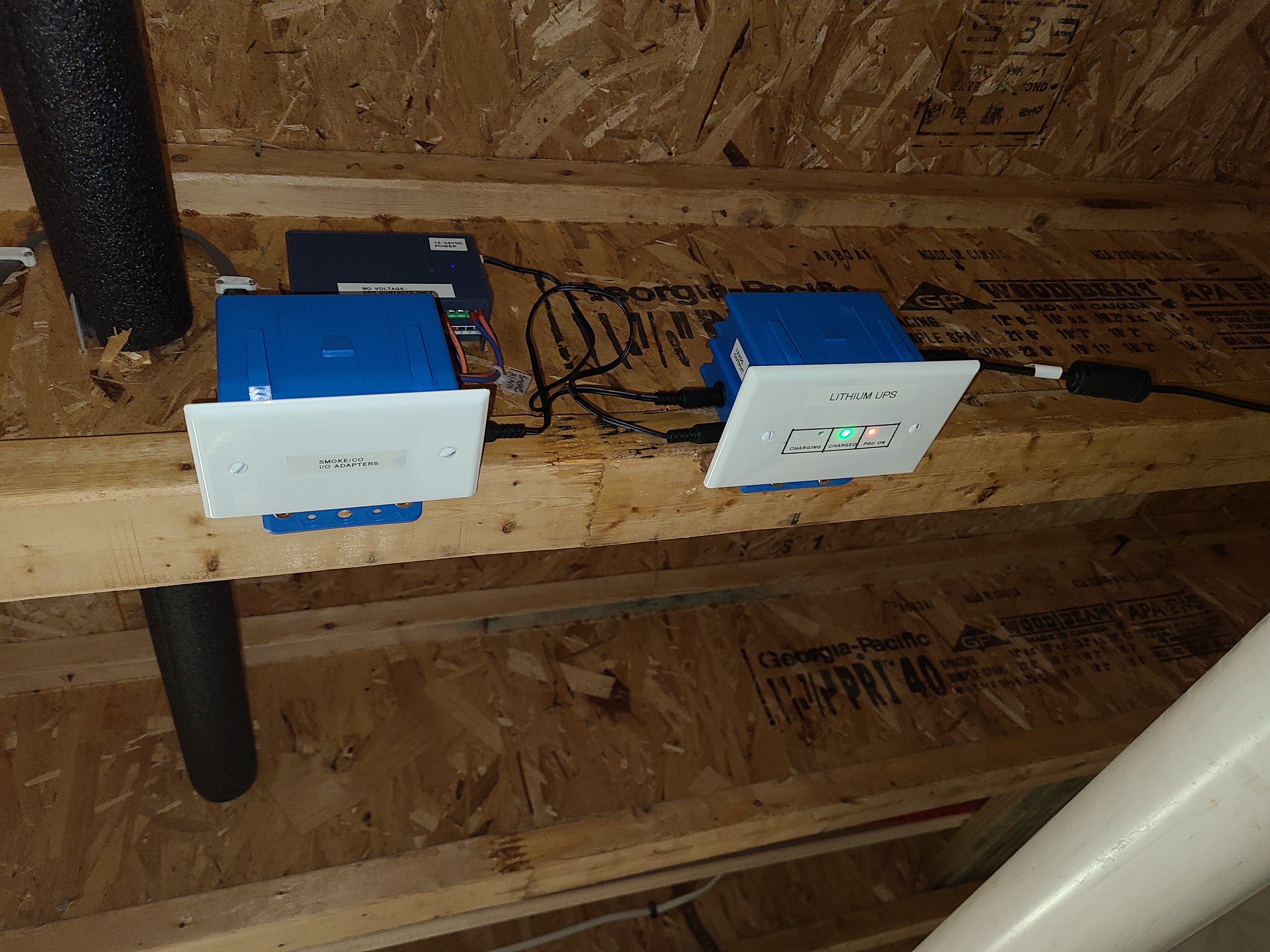
Here is a closeup of the relay box installed next to the UPS and alarm relay box:
With the two above configuration changes, I made two simple HomeAssistant "automations" that simply send my phone a notification when one of the alarms goes off,.
From a blank automation template:
Trigger:
  - type: Device trigger
  - device [choose the dual relay box]
  - Trigger: "Smoke Alarm Becomes Hot"/"CO Alarm started detecting gas" [choose 1]
  - Duration: 1 sec

Action:
  - type: device
  - Device: [choose your phone]
  - Action: Send Notification
  - Message: "SMOKE/CO ALARM HAS ACTIVATED!!"
  - Title: FIRE ALARM